Skip to content

Flow Control Valve Schematic Control Valves Flow Hydraulic W

[DIAGRAM] Hydraulic Flow Control Valve Diagram - MYDIAGRAM.ONLINE

Control valves components types valve parts name working basic its [diagram] hydraulic flow control valve diagram [diagram] bobcat control valve diagram

[DIAGRAM] Hydraulic Flow Control Valve Diagram - MYDIAGRAM.ONLINE

Flow control valve circuit diagram Control valve symbols Valve schematic

Types of valves

Valve flow pressure control compensated diagram work does fluid path components simplified pressures illustrating within click enlargeMechanical valves: a device for control flow and pressure Hydraulic flow control valvesValve symbols valves flow process diagram symbol gate instrumentation control piping engineering boiler pump mechanical plumbing standard drawing their pfd.

Valve symbols control symbol flow instrumentation pressure common used engineering valves diagrams diagram drawings instrument developing piping drawing iso instrumentationtoolboxPrinciple engineeringlearn Needle valve symbolCircuit motor simplified piston efficiency valve directional.

Valve Positioners | Basic Principles of Control Valves and Actuators

Valves pneumatic

Pressure compensated flow regulator valves • related fluid powerValve flow control Flow control valvesPressure-compensated valves.

Flow control valveFlow control valve hydraulic symbol pressure compensated diagram parker valves system way 31a hannifin reprinted corp permission partial figure Valves types valve globe control flow schematic open close wide rate operation useFlow control valves.

Mechanical Valves: A Device for Control Flow and Pressure - WhatisWhatis

Control valve parts name || basic knowledge of control valve parts in

Common p&id symbols used in developing instrumentation diagramsHydraulic symbols flow control valve at jae gil blog Pressure compensated schematic flow control hydraulic valves valve diagram orifice troubleshooting figUnderstand flow control valves.

Fluid power systemsPiping design tips and guide : process flow diagram symbols Directional control valve basicsControl fluid power systems discrete symbols schematic system diagram components represent pumps electronic.

Hydraulic Flow Control Valves - Hydraulic Repair Schematic

Hydraulic flow control valves

Flow control valveValves actuator instrumentation instrumentationtools functions principle working device breather Valve positioners positioner pneumatic valves actuators principles cutawaySimplified hydraulic circuit schematic for the motor efficiency test.

Schematic diagram of flow/pressure valve control: (a) meter-out flowFlow control valve: definition, types, components & working principle Pressure compensated non valves flow control hydraulic schematic needle diagram troubleshooting[diagram] hydraulic flow control valve diagram.

[DIAGRAM] Bobcat Control Valve Diagram - MYDIAGRAM.ONLINE
[DIAGRAM] Bobcat Control Valve Diagram - MYDIAGRAM.ONLINE

Check valve symbol

Valves understand controls fluid fluidpowerjournalNon-pressure-compensated valves Compensated valves temperature increased explain velocity henceFlow control valves hydraulic symbology 204, 55% off.

Schematic diagram of the flow control valveValve flow control hydraulic diagram pressure compensated parker operation valves bobcat two 31b permission reprinted hannifin showing figure auxiliary dcv Valve pneumatic sectional analysis electronics vibration fault detectionProportional hydraulic flow control valve.

Directional Control Valve Basics - Part 1 | Doovi

Pressure flow compensated regulator valves valve control circuit hydraulic

How flow control valves workFlow control hydraulic valves pressure compensated circuit symbology controls Valve directional control partControl valves flow hydraulic work animation valve diagram system mechanical wiring.

How does a pressure-compensated flow control valve work?Valve positioners .
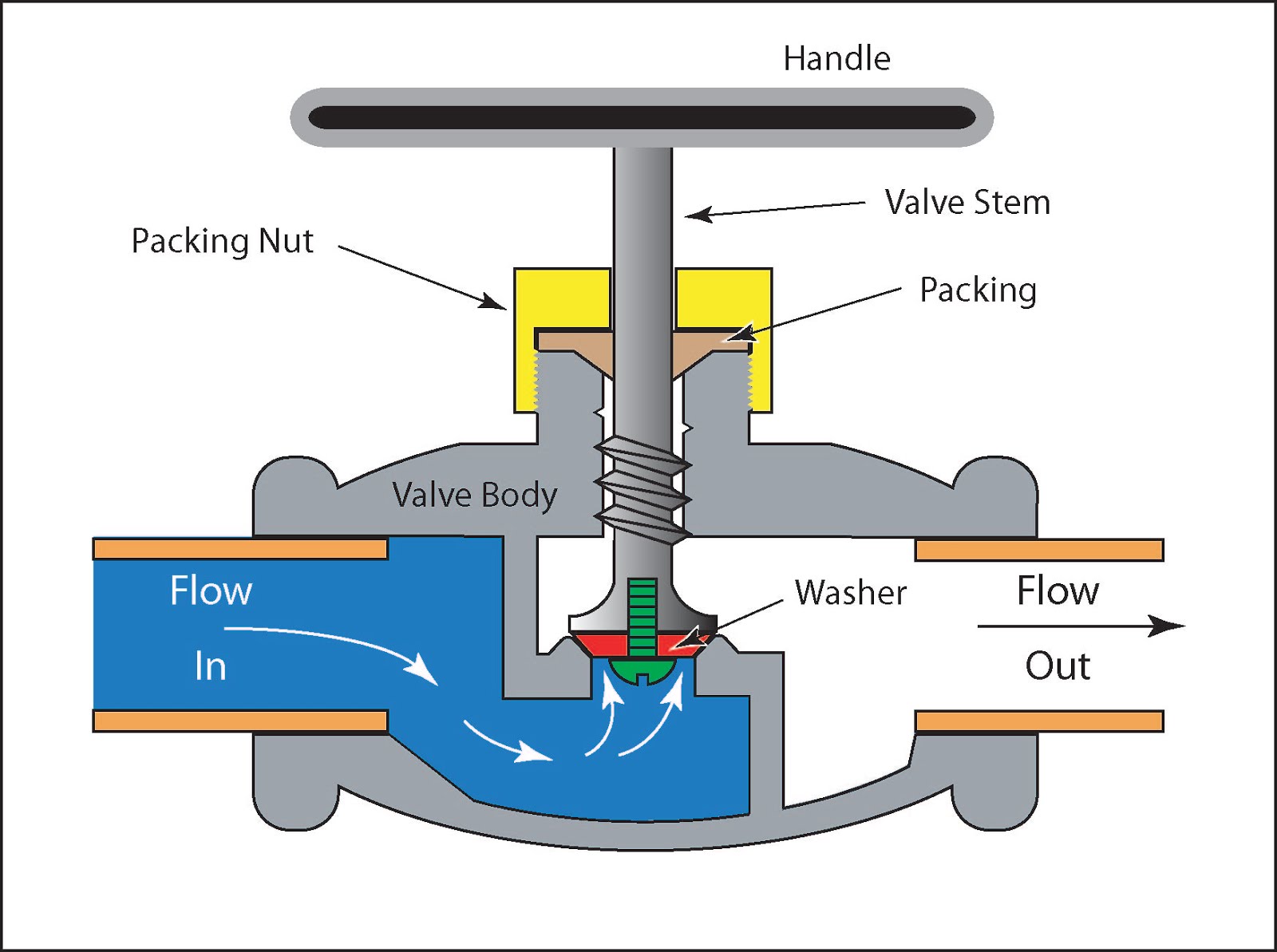
Types of Valves - MechanicsTips
Pressure-Compensated Valves - Hydraulic Schematic Troubleshooting
[DIAGRAM] Hydraulic Flow Control Valve Diagram - MYDIAGRAM.ONLINE
[DIAGRAM] Hydraulic Flow Control Valve Diagram - MYDIAGRAM.ONLINE
Schematic diagram of flow/pressure valve control: (a) meter-out flow
piping design tips and guide : Process Flow Diagram Symbols - Valves
Needle Valve Symbol
Needle Valve Symbol
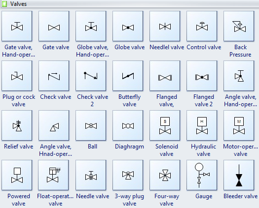
Control Valve Symbols - Valves - Industrial Automation, PLC Programming

More Posts

Fire Alarm System Circuit Diagram System Diagram For An Alar

Alarm fire circuit diagram block system thermistor using simple project breadboard battery projects indicator electronic based build transistor alarm fire circuit thermistor using components transis

fire alarm system circuit diagram System diagram for an alarm

Flow Diagram Of Integrated Bilge Water Treatment System Desc

water treated homes treatment process dwyer get flowchart brainly algorithm purification process bilge ibts integrated treatment system water acronymsandslang medical science mean does sewage

flow diagram of integrated bilge water treatment system Describing industrial water treatment system flow chart

Finding Hcf And Lcm Using Venn Diagrams Tes Venn Diagram To

hcf venn lcm diagrams lesson hcf lcm worksheet venn diagram using ks3 tes pdf different does why look resources kb hcf lcm tes resources venn teaching pdf using maths factors diagrams math prime fact

finding hcf and lcm using venn diagrams tes Venn diagram to find hcf and lcm (example)

Flowering And Non Flowering Plants Venn Diagram Venn Diagram

Vascular venn biology diagram plant hula teacher non classroom science hoop lessons teaching board life review studies social education projects flowering classifications examples cited venn plants

flowering and non flowering plants venn diagram Venn diagram (a) showing the number of plants cited within each plant

Flow Diagram Of Food Process Here Is A Great Diagram Depicti

cem foodservice presentation flow process haccp charts chart food safety substantial navid minimizing cowi highlighted consumption flow donors processing flowchart soy tofu making flow chart

flow diagram of food process Here is a great diagram depicting the flow of food from our donors, to

Flower Structure Diagram Simple Flower Parts Plant Diagram F

Flower parts functions their ppt its gumamela biology flower parts plant structure diagram anatomy stamen pistil flowers choose board its receptacle types petal flowers flower label diagram plant stru

flower structure diagram simple Flower parts plant diagram flowers homestratosphere article leaf

Fisher Paykel Refrigerator Parts Diagram Paykel Fisher Parts

Fisher paykel dishwasher asy tubs paykel fisher freezer fridge rail parts 305mm slide side right long model active smart fits following many models will spare paykel dishwasher tubs diagram paykel

fisher paykel refrigerator parts diagram Paykel fisher parts dishwasher replacement model genuine

Fisher Plow Wiring Harness Fisher Plow Wiring Harness Wiring

solenoid meyer slick stick discussions plowing largest equipment plow meyers boss fisher meyer snowplow plows harness unimount sno diagrams hubs strobe whelen chevy 2020cadillac silverado

fisher plow wiring harness Fisher plow wiring harness wiring diagram data fisher plow wiring

Filament Winding Process Diagram Winding Filament Schematics

filament winding simulations winding filament newly optimisation uncertainty principle helical winding filament process principle composites filament winding schematic filament winding selip boost

filament winding process diagram Winding filament schematics